I took some comparative data of some of the exhaust valves used in double hose regulators.
To take the data I used a Magnehelic and a Dwyer flow meter.
To supply the air flow I used a blower (from a new shop vac that I bought specifically for this type of test) to generate relatively high flow rates.
Notice that I am using air flow at 1 atmosphere, but I am increasing the air flow to higher that realistic values in order to replicate the Reynolds numbers expected at normal diving depths. I don’t have the facilities to test at hyperbaric pressures to increase the air density, but I can increase the air flow and obtain the same Reynolds numbers.
Everyone can understand comparative testing even if you are not following the significance of non-dimensional Reynolds number scaling.
Let me just say that the test conditions are controlled to create a realistic and comparative conditions.
I adjusted the air flow to accurately reproduce the same conditions during all data collection. Only one variable was changed at a time following well established scientific methods for data collection.
Notice that this data is only for steady-state flow. The breathing cycle is closer to a sine wave / transient type of flow.
I tried to also take initial cracking effort (initial valve opening) data, but the numbers tends to be too low to accurately measure. The only observation I can add is that duckbills do tend to stick at times, but I think we have all observed that.
The Magnehelic that I was using only reads up to 5 inWC, therefore I only took data with a pressure delta below or equal to that level. You will see a couple of data points were I could not reach the 10 cfm level without exceeding the 5 inWC limit.
The pressure differential data is just the raw data as I read it. Some of it was expected, but some was a bit of a surprise.
The data was very easy to take with one exception, the silicone duckbill fluttered a lot with 10 cfm of flow. This caused the needle to move wildly. The reading shown was my best average of the fluctuating gauge.

Here are the test samples.
The Argonaut can is a 3D printed prototype. It is intentionally blurred in the pictures for a couple of reasons… There will be more pictures of the new cans in the near future.

Here is part of the test set –up.
Attached in this picture is the can with no valve used as a baseline for comparison testing.


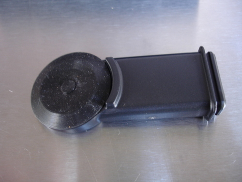
Here is the Scubapro 109 connected for testing.

I bought this little vacuum cleaner specifically to use id as a blower for this type of testing (either for blowing or to generate suction/ vacuum).